Filtered antennas (UNA class)
They suppress out-of-band interference but do not form spatial nulls toward the source. Against in-band directional jamming their help is limited.
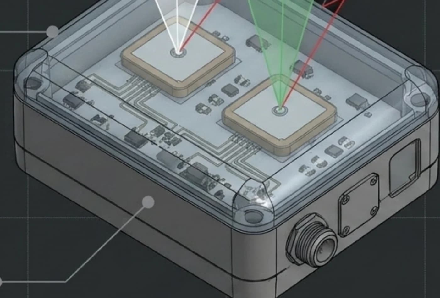
NullWave is a family of digital CRPA antennas that adaptively null the jammer by direction while keeping the satellites in view. Full CRPA capability at mass-platform component cost.
Land · Sea · Air — UAV, UGV, USV
TRL 6
Production readiness
0.0
dBµV/m — peak field strength in testing
2 / 4 / 8
Elements across the lineup
1
Cable: power + data
Certified immunity: 95.6 dBµV/m (acceptance condition per technical specification). 102.7 dBµV/m is the peak value recorded during range testing.
01 / The problem
The signal arriving from orbit is extremely weak. A ground jammer of modest power blinds a receiver tens of kilometres away. A conventional antenna — even a filtered one — loses its fix exactly inside the mission area. The result: a failed mission and a lost platform with its payload.
They suppress out-of-band interference but do not form spatial nulls toward the source. Against in-band directional jamming their help is limited.
They work — but they are multi-channel systems costing thousands of dollars, designed for manned aviation. On a mass-produced platform they are economically impossible.
A complement, not a replacement. More expensive, requires integration into flight logic, and does not restore a satellite fix.
The empty niche
Full CRPA capability — adaptive directional suppression — at mass-market price.
02 / Technology
Several spatially separated receiving elements pick up the same signal at different phases. The processor computes complex weight coefficients and combines the channels so that a null in the reception pattern forms toward the jammer. The satellites stay in view.
Drag the jammer around the circle
Two (four, eight) coherent L1 RF channels sharing a reference oscillator and clock. Streaming IQ data.
Amplitude and phase alignment of the receive chains through a test input on the antenna board, inter-channel compensation, sample synchronisation. Without this, the null drifts.
Estimation of the input covariance matrix, computation of weight coefficients, adaptive null forming toward the interference sources. Method class: power-inversion / MVDR.
The cleaned signal feeds a standard GNSS receiver. UART exchange over the UBX protocol, with C/N0 and fix-status monitoring.
Architecture
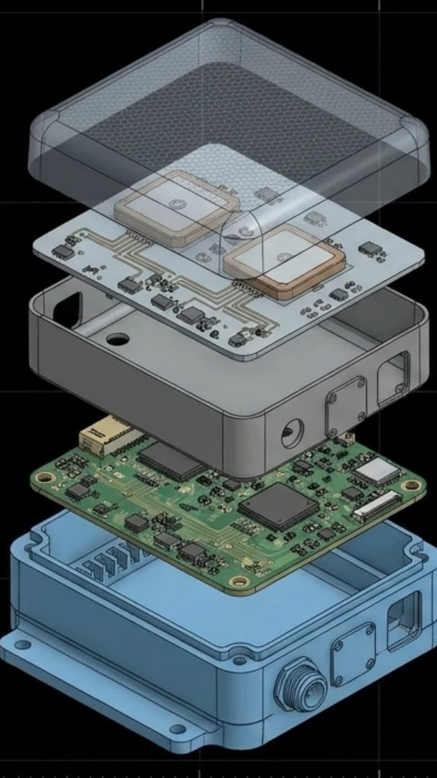
Real-time DSP on a Zynq-class SoC/FPGA. Mathematical model: power-inversion / MVDR. Performance is defined by the algorithm, not by an analogue chain.
When the adversary changes the jamming type, we respond with a firmware update. An analogue CRPA would need a new product.
The RF layer sits on top under a radio-transparent radome; the digital layer sits below under metal. The housing acts as a shield between them, keeping computing noise out of the receive chain.
Proprietary algorithms and processing pipeline. The supply chain carries no critical foreign dependency in algorithms, antenna block or firmware.
| Classic analogue CRPA | NullWave (digital) | |
|---|---|---|
| Where the null forms | In the analogue chain, in hardware | In DSP on FPGA/SoC |
| Adapting to a new jammer type | Hardware replacement or redesign | Firmware update |
| Array scaling | A new product | Same logic, different array layout |
| Price class | Thousands of dollars | Mass-platform component level |
03 / Evidence
UNA-3CSFE+ SW54
Loses its fix at 100 m from the emitter
NullWave 2
Holds its fix confidently at 5 m from the emitter
Illustrative representation of behaviour observed in head-to-head testing
Head-to-head comparison per the CRPA-TEST-001 protocol. Full test conditions — emitter type, power, frequency, altitude and platform configuration — available on request under NDA.
95,6
Certified immunity
102,7
Peak value in testing
Confirmed operation under intentional interference at field strengths up to 95.6 dBµV/m — the acceptance condition defined in the technical specification. The peak value at which the unit continued to output a fix during testing was 102.7 dBµV/m.
The product has been used on heavy strike multirotors along an active front line. Missions were completed with the antenna in the loop, and crews reported positively. Direct hits on the antenna itself were recorded — the unit was flying on combat platforms.
Differentiator
A jammed receiver at least reports that it has no fix. A spoofed one confidently outputs a false one. The autopilot trusts it and flies the platform to a point that does not exist.
NullWave firmware identifies signs of signal spoofing and stops issuing a navigation solution instead of handing over a false position. Available on the two-element configuration.
For four-element configurations and above, spatial rejection of the spoofing source with recovery of the true position is in development.
Anti-spoofing arrived as a firmware update for units already in the field. That is the practical proof of the digital architecture's advantage.
Unprotected
The platform accepts the false fix and flies to a point that does not exist
With NullWave
Spoofing detected, the false solution is rejected
04 / Build
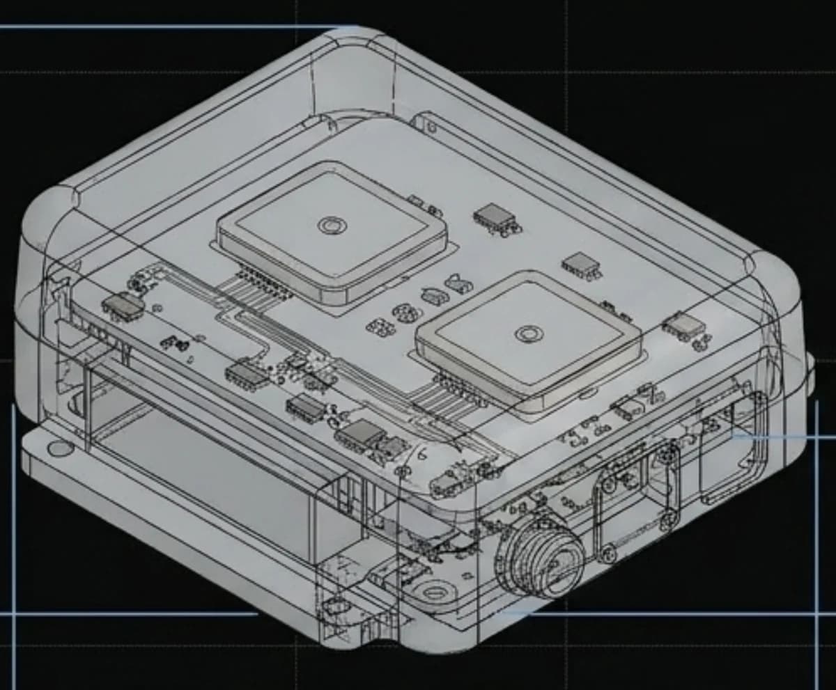
Radio-transparent radome; internal ribs hold the antenna board and set a repeatable gap above the patches
Two ceramic patches, 35 × 35 × 6.5 mm, separated along the long axis
The metal partition shields the digital layer from the receive chain
SDR module with a heatsink pressed against the housing — the housing doubles as a heat path
InterfaceCup gland: one cable carries both power and data
Perimeter mounting ears — attaches to the platform frame without adapter plates
Both channels are mirrored with equal trace lengths. Calibration is a correction, not a rescue of poor routing.
Patches and LNAs sit close together — noise figure is not eaten by cabling, and path-length difference stays minimal, which is critical for phase coherence.
M3 screw assembly, no soldering or adhesive. Bought-in modules sit on connectors and swap without rework. The antenna board comes out separately.
Milled 6061 aluminium, bead-blasted and anodised. Simultaneously mechanical protection, EM shield and thermal path.
Specification
A complete design documentation package (Altium, SolidWorks) is ready for transfer to a contract manufacturer. Screw assembly, no soldering or adhesive.
05 / Lineup
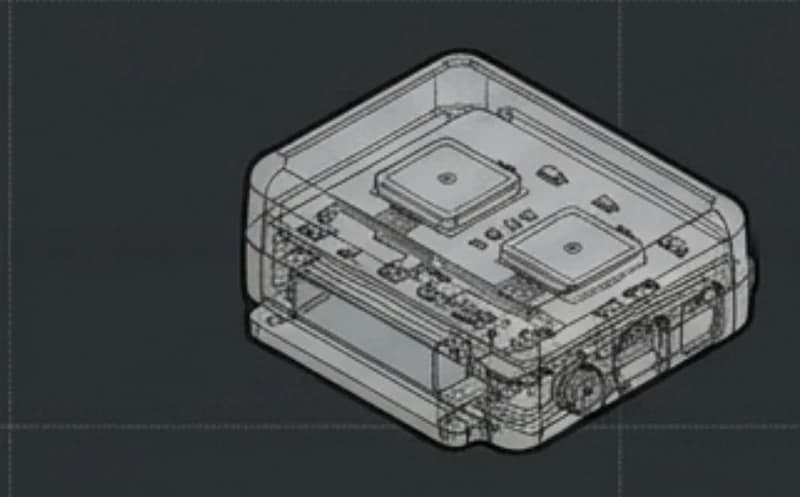
Production-ready and combat-proven. Optimal for mass-produced FPV, light UAVs, ground robotic systems and unmanned surface vessels.
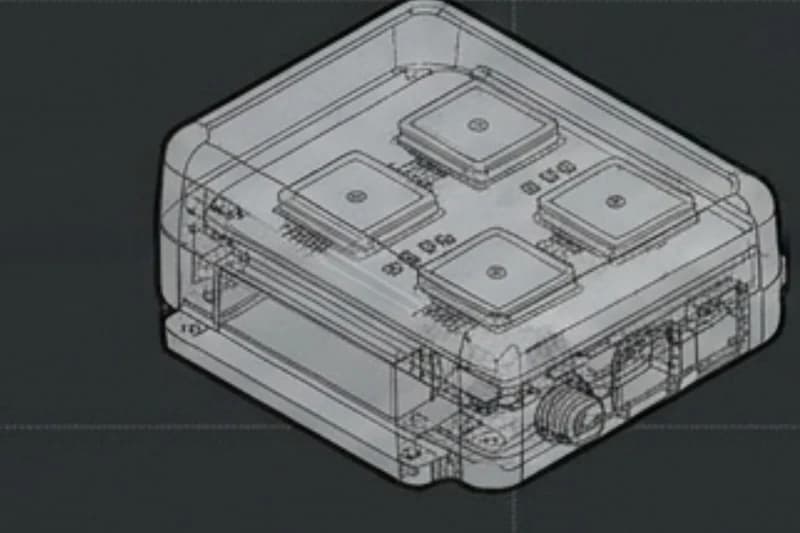
The processor is integrated onto a proprietary board, lowering unit cost. Handles multiple simultaneous jamming sources. Platform class: medium UAVs, heavy hexacopters, USVs.
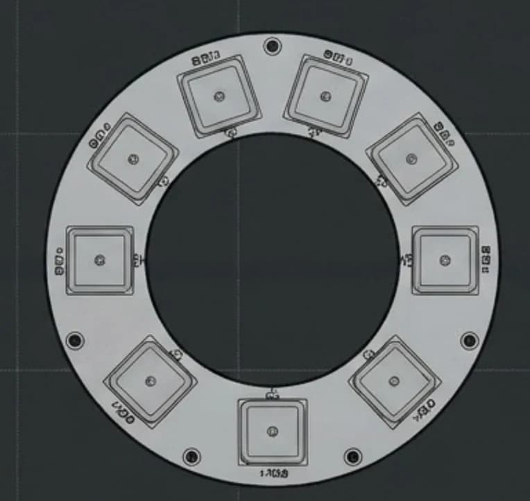
A circular multilayer board carrying eight ceramic patches around its circumference: uniform azimuthal coverage with no blind sectors and the maximum number of steerable nulls. Target class: large UAVs, special-purpose and maritime platforms.
The digital processing core is shared across the family. Moving between configurations changes the array layout and channel count, not the algorithm.
06 / Integration
Perimeter mounting ears, M3 fixings straight onto the platform frame. No adapter plates required.
Power and data share one sealed gland. On the platform that means a single entry instead of a harness.
UART exchange over the UBX protocol. The autopilot receives its usual navigation solution — nothing needs rewriting.
07 / Methodology
The company operates a formalised head-to-head comparison methodology — protocol CRPA-TEST-001. The methodology is agreed and signed with the customer before testing begins; the results are signed afterwards. KPIs are computed from logs, not judged by eye.
Both antennas outside the control loop — we compare what each one actually outputs.
Sub-variants with the flight controller on the reference antenna and on the device under test: does the platform hold position.
LOITER under L1 jamming with power stepped up every 30 seconds — up to loss of the navigation solution.
KPIs recorded
Satellite count · HDOP · C/N0 · position σ in hover · altitude σ · fix losses · EKF innovation · J/S threshold · time to reacquisition (TTRA)
Processing runs from flight-controller and secondary-receiver logs; the KPI computation script is version-controlled and available to the customer.
Test protocol
CRPA-TEST-001 v1.1
Methodology agreed
Test results
Customer signature
Contractor signature
Signed twice: before and after testing
For investors
Hundreds of thousands of mass-produced unmanned platforms for which classic Western CRPA is financially out of reach. Every GNSS-equipped platform operating under jamming is a unit of demand.
Direct B2B contracts with unmanned-platform manufacturers, plus licensing of the digital processing technology.
Full-stack development — from RF circuit design and mechanical construction to FPGA programmable logic and real-time adaptive filtering algorithms.
The advantage lies in the algorithm and the layout, not in bought-in components. Implementation rights belong to the company.
Use of proceeds
Scaling NullWave 2 into series production, and funding the R&D stages and prototype runs of NullWave 4 and NullWave 8.
Questions
A filtered antenna suppresses out-of-band interference but forms no spatial nulls. NullWave determines the direction of the source and adaptively steers a null toward it while continuing to receive satellites.
No. Exchange runs over UART using the UBX protocol, so the autopilot receives its usual navigation solution. Integration is mechanical mounting plus one cable.
GNSS L1, 1559.05–1605.66 MHz. The chain is single-band.
The number of steerable nulls follows the number of array elements. The two-element configuration addresses one dominant source; four- and eight-element configurations handle several at once.
The firmware detects signs of signal spoofing and stops issuing a navigation solution rather than handing over a false position. Spatial rejection of the spoofing source with recovery of the true position is in development for four-element configurations and above.
NullWave 2 is at TRL 6 — a field-tested engineering unit, production-ready, with a complete design documentation package. NullWave 4 is a prototype; NullWave 8 is in R&D.
Through the form on this page. We agree the CRPA-TEST-001 test methodology before testing begins, hand over the unit and support the pilot integration.
Yes, under NDA. Send a request through the form, specifying your platform and use case.
Contact
Tell us about your platform and we will come back with a proposed configuration, test conditions and timeline.
You submit a request describing your platform and use case
We agree the test methodology before the unit ships
We run joint testing and record the outcome in a signed protocol